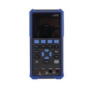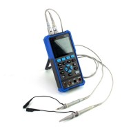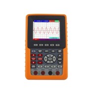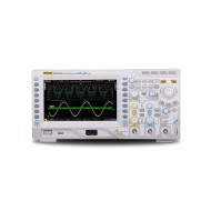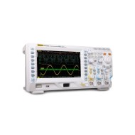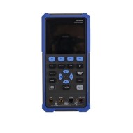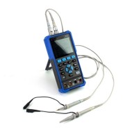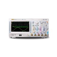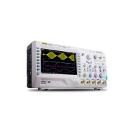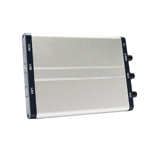
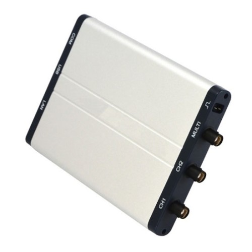


25 MHz Socoje PC Based Oscilloscope Dual Channel 100 MSa/s 1pc
from
$750.95
Ex Tax: $750.95
- Stock: In Stock
- Model: SCJ009641
- SKU: SCJ009641
Products Sold: 0
Product Views: 634
Available Options
Ask a Question About This Product
- Description
25 MHz Socoje PC Based Oscilloscope Dual Channel 100 MSa/s 1pc
Brief
Lower cost PC-based oscilloscope is a high-accuracy dual-channel digital oscilloscope with 25 MHz bandwidth, 100 MSa/s sampling rate. The waveform of PCO can be recorded/saved, and the maximum storage is 4000M, which can be read at any time.
Description
The 25 MHz PC oscilloscope with 100 MSa/s sampling rate, 2 analog channels, 5K record length, fast acquisition speed, and general test requirements can be met. Dual-channel virtual oscilloscope, the detected waveform can be displayed on the computer, image storage, display on the same screen and another multi-function computer virtual oscilloscope.
Specification
| Model | SCJ009641 | SCJ009641I |
| Max. Input Voltage | 40V(DC + AC peak) | 400V(DC + AC peak) |
| Communication Interface | USB2.0 | USB2.0 (isolation) |
| Bandwidth | 25 MHz | |
| Channel | 2 Channel+ Multi | |
| Sample Rate | 100 MSa/s | |
| Horizontal Scale (s/div) | 5ns/div - 100s/div, step by 1 - 2 - 5 | |
| Record Length | 5K | |
| Input Impedance | 1MΩ ± 2%, in parallel with 10pF ± 5pF | |
| Vertical Sensitivity | 5mV/div - 5V/div | |
| Vertical Resolution | 8 bits | |
| Trigger Type | Edge, Pulse, Video, Slope, and Alternate | |
| Automatic Measurement | Vpp, Vavg, Vrms, Frequency, Period, Vmax, Vmin, Vtop, Vbase, Vamp, Overshoot, Pre-shoot, Rise Time, Fall Time, +Width, -Width, +Duty, -Duty, DelayA→B , DelayA→B | |
| Waveform Math | +, -, *, /, FFT | |
| Power Supply | ≤2.5W | |
| Dimension (W * H * D) | 170* 18* 120mm | |
| Weight | 0.26 kg | |
Accessories
- Power cord
- CD rom
- USB cable
- Probe
- Probe Adjust
- Multimeter lead
- Adapter
- User manual
- 5V, 1KHz Output
- Capacitance Ext Module
- Soft Bag
- Metal Case (optional)
Dimension (mm)

Tips: How to use a PC-based oscilloscope?
- Pre-adjust first: turn the luminance knob counterclockwise to the end, turn the vertical and horizontal displacements to the middle, set the attenuation to the highest level, and set the scan to the "outer X position".
- Turn on the power again, wait for a minute or two to warm up after the indicator light is on, and then perform related operations.
- Adjust the brightness first, then adjust the focus, and then adjust the horizontal and vertical displacement to make the bright spot in the central area.
- Adjust the scan, scan fine-tuning and X gain, and observe the scan.
- Unplug the outer X gear to the appropriate position of the scanning range gear, and observe the voltage waveform provided by the machine in the vertical direction that changes according to the law of sine and cosine.
- Connect the external voltage to be studied to the oscilloscope indirectly from the Y input and the ground, adjust each gear to a suitable position, and observe the waveform of this voltage (image changing with time) (adjusting the synchronous polarity switch can make the image The starting point starts from the positive half cycle or the negative half cycle.
- If you want to observe the vertical offset of bright spots (such as when a DC voltage is applied), you can adjust the scan to "outer X".
- Reviews
