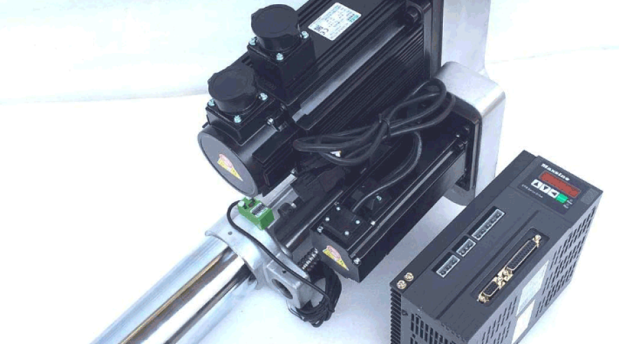
The power heads currently in use have only one coordinate feed. If two coordinates are required to work, a cross slide is needed to achieve this. However, this method has relatively low work efficiency, and the processing accuracy is not high. It also requires manual operation, increasing labor costs.
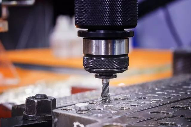
The technical problem is: providing a cost-saving, high-precision, and easy-to-operate threaded power head to address the various defects and shortcomings of existing technologies.
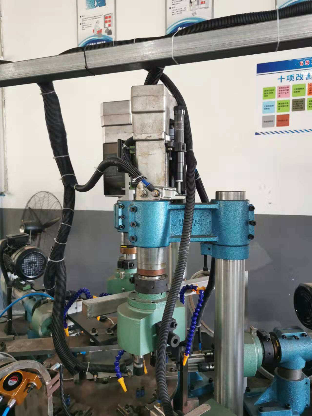
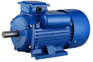
The technical solution is: a threaded power head, including a motor, a shaft sleeve, a shaft, and a protective sleeve. The motor is equipped with a pulley, and the pulley is connected to the shaft sleeve via a transmission belt. The shaft sleeve is mounted on the shaft, and an adjusting sleeve is installed between the shaft sleeve and the shaft. The adjusting sleeve is mated with the shaft via interference fit, and it is connected to the shaft sleeve via a spline. The shaft and the shaft sleeve are covered with a protective sleeve. One end of the shaft is equipped with a threaded rod, which is threaded with a nut fixedly installed on the protective sleeve. The other end of the shaft is equipped with a fixture.
Working principle: Install the cutter head on the fixture, start the motor, and drive the shaft sleeve to rotate through the transmission belt. The shaft sleeve drives the adjusting sleeve to rotate via the spline, and the adjusting sleeve drives the shaft to rotate. At this time, the cutter head rotates, and meanwhile, the threaded rod rotates. Due to the fixation of the nut, the threaded rod engages with the nut, causing the shaft to move forward, and the cutter head achieves feed cutting. After cutting is completed, the motor reverses, and the cutter head returns to its initial position.
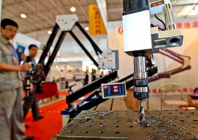
Advantages:
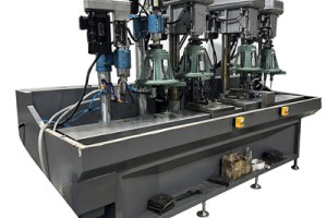
Machine tool functions can be achieved with a single power head, saving floor space.
Simplify the machine tool structure and reduce production costs.
Multiple power heads can be used to achieve multi-process machining, facilitating combination and saving equipment investment.
Design of Threading Power Head Structure
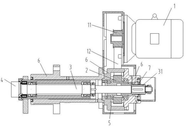
Motor 1, shaft sleeve 2, shaft 3, and protective sleeve 6. The motor 1 is equipped with a pulley 11, and the pulley 11 is connected to the shaft sleeve 2 via a transmission belt 12. The shaft sleeve 2 is mounted on the shaft 3, and an adjusting sleeve 5 is installed between the shaft sleeve 2 and the shaft 3. The adjusting sleeve 5 is mated with the shaft 3 via interference fit, and it is connected to the shaft sleeve 2 via a spline. The shaft 3 and the shaft sleeve 2 are covered with a protective sleeve 6. One end of the shaft 3 is equipped with a threaded rod 31, which is threaded with a nut 7 fixedly installed on the protective sleeve 6. The other end of the shaft 3 is equipped with a fixture 4. Install the cutter head on the fixture 4, start the motor 1, and drive the shaft sleeve 2 to rotate through the transmission belt 12. The shaft sleeve 2 drives the adjusting sleeve 5 to rotate via the spline, and the adjusting sleeve 5 drives the shaft 3 to rotate. At this time, the cutter head rotates, and meanwhile, the threaded rod 31 rotates. Due to the fixation of the nut 7, the threaded rod 31 engages with the nut 7, causing the shaft 3 to move forward, and the cutter head achieves feed cutting. After cutting is completed, the motor 1 reverses, and the cutter head returns to its initial position.
Leave a comment