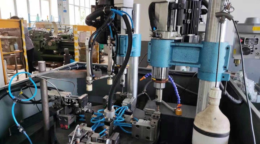
The servo hole enlarging and tapping power head includes a rotating mechanism and a feeding mechanism. The rotating mechanism is equipped with a motor, and the motor's pulley is connected to the bearing sleeve through a transmission belt. The bearing sleeve is connected to the rotating shaft via a spline. The rotating shaft is equipped with a shaft sleeve, and an protective sleeve is installed on the outside of the shaft sleeve. One side of the protective sleeve has an opening. A fixture is provided at one end of the rotating shaft, and the fixture is installed on the outside of the protective sleeve and fixed to the shaft sleeve with screws. The feeding mechanism is installed on one side of the rotating mechanism. The feeding mechanism is equipped with a servo motor, and the servo motor is connected to a screw rod. A movable nut is mounted on the screw rod, and the movable nut is fixedly connected to a movable rod. One end of the movable rod is fixedly installed on the rotating shaft via a spline.
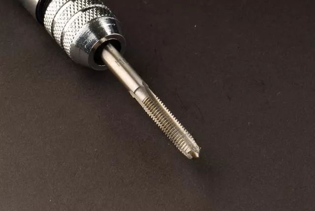
Operating Principle:
A cutter head is installed on the fixture. When the motor starts, the bearing sleeve rotates via the transmission belt, driving the rotating shaft to rotate. At this time, the cutter head rotates. Meanwhile, the servo motor operates, driving the screw rod to rotate. The rotation of the screw rod drives the movable nut to move forward, which in turn moves the movable rod. The movable rod drives the rotating shaft to advance, completing the feeding and cutting work of the cutter head. After cutting is completed, the servo motor rotates in the opposite direction, and the cutter head returns to its original position.
Advantages:
- With only one power head, the functions of the machine tool can be realized, saving floor space.
- Simplify the structure of the machine tool and save production costs.
- By equipping multiple power heads, multi-process machining can be achieved, which is convenient for combination and saves equipment investment.
Servo Motor-driven Hole Enlarging and Tapping Power Head
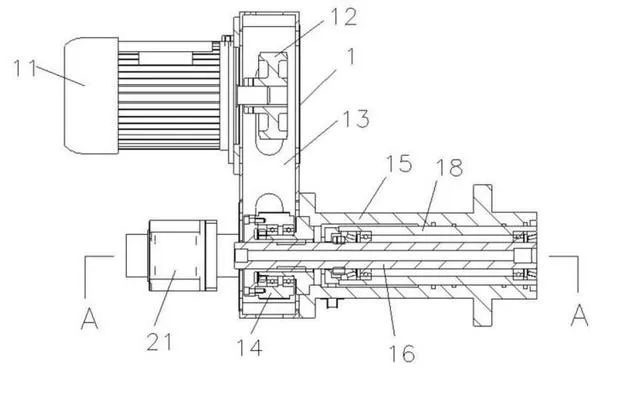
The rotating mechanism (1) and the feeding mechanism (2) are comprised of several components. The rotating mechanism (1) includes a motor (11), where the motor's pulley (12) is connected to a bearing sleeve (14) via a transmission belt (13). The bearing sleeve (14) is connected to the rotating shaft (16) through a spline, while the rotating shaft (16) is equipped with a shaft sleeve (18) and an protective sleeve (15) installed on its outer side. The protective sleeve (15) has an opening on one side. A fixture (17) is provided at one end of the rotating shaft (16), and it is installed on the outer side of the protective sleeve (15) and fixed to the shaft sleeve (18) with screws. The feeding mechanism (2) is mounted on one side of the rotating mechanism (1) and includes a servo motor (21) connected to a screw rod (24). A movable nut (22) is mounted on the screw rod (24), which is fixedly connected to a movable rod (23). One end of the movable rod (23) is fixedly installed on the rotating shaft (16) via a spline.
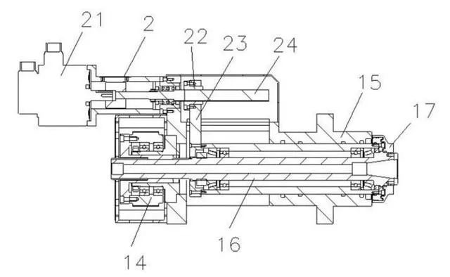
A cutter head is installed on the fixture (17). When the motor (11) starts, the bearing sleeve (14) rotates via the transmission belt (13), driving the rotating shaft (16) to rotate. This rotation causes the cutter head to rotate. Simultaneously, the servo motor (21) operates, driving the screw rod (24) to rotate. The rotation of the screw rod (24) moves the movable nut (22) forward, which in turn moves the movable rod (23). The movement of the movable rod (23) drives the rotating shaft (16) to advance, allowing the cutter head to perform feeding and cutting operations. Once the cutting process is completed, the servo motor (21) rotates in the opposite direction, and the cutter head returns to its initial position.

Leave a comment