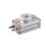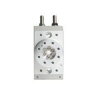


6mm-32mm Bore Size Pneumatic Gripper, Double Acting 1pc
from
$69.54
Ex Tax: $69.54
- Stock: In Stock
- Model: SCJ009694
- SKU: SCJ009694
Products Sold: 0
Product Views: 219
Available Options
Ask a Question About This Product
- Description
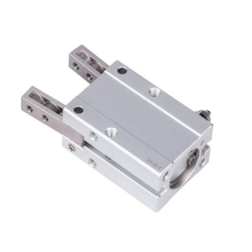
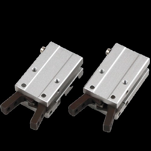
6mm-32mm Bore Size Pneumatic Gripper, Double Acting 1pc
Brief
High precision pneumatic 2 finger angular grippers are available in a wide range of sizes and configurations with optional bores such as 6mm, 10mm, 16mm, 20mm, 25mm and 32mm. Equipped with a double acting cylinder for control, this featured device has the ability to grip a variety of workpieces and its gripping force is adjustable.
Description
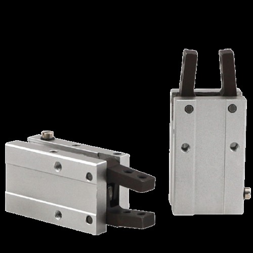
Pneumatic grippers, also known as air grippers, are a multi-axis pick & place solution that uses compressed air to operate gripper jaws. These robust grippers available from SOCOJE provide three mounting positions with the mounting holes on the side, bottom and front of the gripper body, therefore delivering flexible applications. A number of bore sizes are supplied for your selection with minimum size being 6mm and maximum one being 32mm. Single piston structure creates large gripping torque.
Product features:
- Six kinds of bore size with various specifications for selection.
- Equipped with reasonable gripping angles suitable for wide applications.
- Mounting holes are subtly arranged on the side and tail, which facilitates installation from different directions.
- Designed with a single piston structure generating large gripping torque
- Integrated with variable flow valve, convenient to adjust the opening and closing speed of gripping jaws.
- Precise positioning brings more accurate gripping of workpieces.
- Embedded with magnetic switch slots, making it easy to install inductive switches.
Specifications:
| Model | SCJ009694 | ||||||
| Bore size | 6mm | 10mm | 16mm | 20mm | 25mm | 32mm | |
| Acting type | Double acting | ||||||
| Fluid | Air (to be filtered by 40 um filter element) | ||||||
| Operating pressure | 0.15~0.7MPa (22~100psi) (1.5~7.0bar) | ||||||
| Temperature | -20~70℃ | ||||||
| Lubrication | Cylinder: Not required; Gripper jaws: Lubricate grease | ||||||
| Cushion type | Bumper | ||||||
| Max. frequency | 180 (c.p.m) | ||||||
| Sensor switches* | CMSH/DMSH (S) | CMSG/DMSG (S) | |||||
| Port size | M3 × 0.5 | M5 × 0.8 | |||||
| Weight | 1Kg | ||||||
| Note: Sensor switch should be ordered additionally. | |||||||
Gripping force and stroke:
| Bore size | 6 | 10 | 16 | 20 | 25 | 32 | |
| Theoretical gripping torque (N•cm) | Closed | 7.4×P | 17.6×P | 90×P | 152×P | 304×P | 637×P |
| Opened | 10.6×P | 29.4×P | 129×P | 252×P | 473×P | 904×P | |
| Max. length of gripping point (L) | 30mm | 30mm | 40mm | 60mm | 70mm | 85mm | |
| Opening angle | 30°+3 | ||||||
| Closing angle | -10°-3 | ||||||
| Note: The P in the gripping torque shown in the above chart represents the actual use of air pressure. | |||||||
Inner structure and material of major parts:
| NO. | Item | Material | |
| 1 | Gripping jaws | Carbon steel | |
| 2 | Pin | Stainless steel | |
| 3 | Front cover | Aluminum alloy | |
| 4 | Rod packing | NBR | |
| 5 | Piston rod | Aluminum alloy/Stainless steel | |
| 6 | Bumper | TPU | |
| 7 | Countersink crew | Carbon steel | |
| 8 | Magnet washer | NBR | |
| 9 | Piston | Aluminum alloy/Stainless steel | |
| 10 | Bumper | TPU | |
| 11 | C clip | Spring steel | |
| 12 | Back cover | Aluminum alloy | |
| 13 | Steel ball | Stainless steel | |
| 14 | O-ring | NBR | |
| 15 | O-ring | NBR | |
| 16 | Screw cap | Carbon steel | |
| 17 | Adjustable nut | Brass | |
| 18 | Fixed nut | Brass | |
| 19 | O-ring | NBR | |
| 20 | Piston seal | NBR | |
| 21 | Magnet | Sintered metal (Neodymium-iron-boron) | |
| 22 | Body | Aluminum alloy | |
| 23 | Countersink crew | Carbon steel | |
| 24 | Pin | Stainless steel | |
| 25 | Pin sheath | Stainless steel | |
| 26 | Magnet fixed flake | Stainless steel | |
| 27 | O-ring | NBR | |
Dimensions (unit=mm):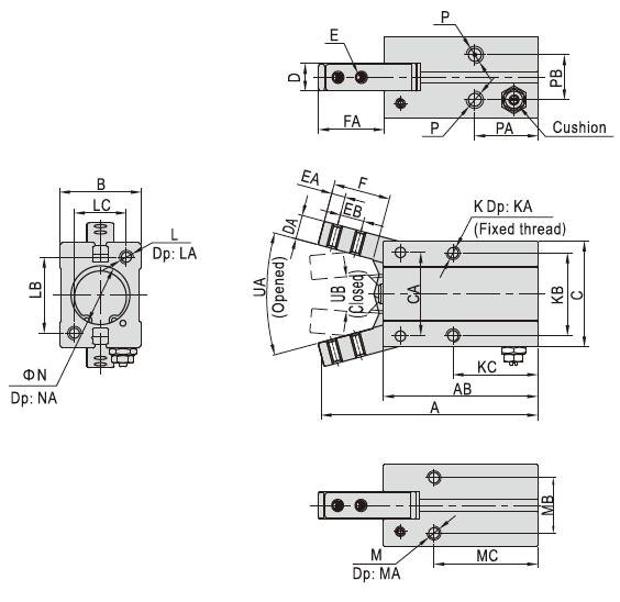
| Bore size/Item | A | AB | B | C | CA | D | DA | E | EA | EB | F | FA | K | KA | KB | KC | L |
| 6 | 47.5 | 36 | 10.5 | 20 | 14 | 4 | 4 | M2×0.4 | 2.5 | 5 | 11 | 12 | M3×0.5 | Thru. Thread | 12 | 26 | - |
| 10 | 52.5 | 38.5 | 16.5 | 23 | 14 | 6.4 | 4 | M2.5×0.45 | 3 | 5.7 | 12 | 14.5 | M3×0.5 | 5 | 16 | 23 | M3×0.5 |
| 16 | 62.5 | 44.5 | 23.5 | 30.5 | 24 | 8 | 7 | M3×0.5 | 4 | 7 | 16 | 19 | M4×0.7 | 7 | 24 | 24.5 | M4×0.7 |
| 20 | 78 | 55 | 27.5 | 42 | 30 | 10 | 8 | M4×0.7 | 5 | 9 | 20 | 23.5 | M5×0.8 | 8 | 30 | 29 | M5×0.8 |
| 25 | 92 | 60.5 | 33.5 | 52 | 36 | 12 | 10 | M5×0.8 | 8 | 12 | 27 | 33 | M6×1.0 | 10 | 36 | 30 | M6×1.0 |
| 32 | 96.5 | 68 | 40 | 60 | 42 | 18 | 10 | M6×1.0 | 6 | 14 | 27 | 29.5 | M6×1.0 | 10 | 44 | 37.5 | M6×1.0 |
| Bore size/Item | LA | LB | LC | M | MA | MB | MC | N | NA | P | PA | PB | UA (Opened) | UB (Closed) |
| 6 | - | - | - | - | - | - | - | 7+0.05 | 1.5 | M3×0.5 | 19 | 1.5 | 30° | 10° |
| 10 | 6 | 18 | 12 | M3×0.5 | 6 | 11.5 | 27 | 11+0.05 | 1.5 | M3×0.5 | 19 | 10 | 30° | 10° |
| 16 | 8 | 22 | 15 | M4×0.7 | 8 | 16 | 30 | 17+0.05 | 1.5 | M5×0.8 | 18.5 | 13 | 30° | 10° |
| 20 | 10 | 32 | 18 | M5×0.8 | 10 | 18.5 | 35 | 21+0.05 | 1.5 | M5×0.8 | 22 | 15 | 30° | 10° |
| 25 | 12 | 40 | 22 | M6×1.0 | 10 | 22 | 36.5 | 26+0.05 | 1.5 | M5×0.8 | 23.5 | 20 | 30° | 10° |
| 32 | 12 | 46 | 26 | M6×1.0 | 10 | 26 | 30 | 34+0.05 | 2 | M5×0.8 | 31 | 24 | 30° | 10° |
Tips: How to select the right product?
- The selection of the gripping force
The gripping work-pieces shown below, against the impact caused by ordinary handling, when safety coefficient a=4, have a gripping force that is more than 10-20 times of the mass of the gripped objects.
When gripping work-pieces as shown in the left: u=0.2 u=0.1 F: Gripping force (N)
u: Friction coefficient between fittings and work-pieces
m: Mass of work-pieces
g: Acceleration of gravity (=9.8m/s2)The condition that the work-pieces won't drop is:
2×uF>mg
so: F>mg/(2×u)
Safety coefficient is a, so F is:
F=[mg/(2×u)]×aF=[mg/(2×0.2)]×4=10×mg F=[mg/(2×0.1)]×4=20×mg 10 times of the mass of
the gripped objects20 times of the mass of
the gripped objectsNote) If the friction coefficient u>0.2, for safety, please keep to the above principle of selecting clamping force 10 to 20 times larger than the mass of the clamped objects. When it comes to large acceleration and impact, reserving larger safety coefficient is a must. - The selection of the gripping point
When the gripping force is determined, decide the gripping point according to the defined ranges shown in charts below. If the point goes beyond the range, the gripping jaw will be subjected to excessive load moment, shortening the life of pneumatic grippers.


Precautions for Installation and Application:
- Due to the abrupt changes, the pressure is low, which may result in the decrease of gripping force and the falling of the work-pieces, thus doing harm to humans and damage to equipment. To get rid of that, anti-dropping device must be equipped.
- Don’t use the air gripper against rather strong external force and impact force.
- Do avoid dropping, collision and damage amid the installation and fixing of the pneumatic gripper.
- Don’t twist the gripping jaw when securing the fittings.
- There are several installation methods shown as follows, and make sure that the torque of fastening screws should be within the specified moment range as the locking moment being too large will cause malfunction while it being too small will cause position deviation and fall.


- The installation method of the gripping jaw fittings:It deserves special attention when you install the gripping jaw fittings that you can only hold the gripping jaw by using a spanner, and then tighten the screws with an Allen wench. Never clamp the body directly and then lock the screws, otherwise the parts will be easily damaged.

- When gripping a work-piece, the work-piece must be located in the center line of the two gripping jaws, and the two gripping jaws also need to touch the work-piece at the same time, otherwise the gripping jaws will be easily damaged.
- Make sure that there is no additional external force applied to the gripping jaws. Transverse load being exerted on the gripping jaws will produce impact load, causing wobble and damage to the gripping jaws. Keep enough gaps so that the air gripper will not crash into work-pieces and accessories at the end of its stroke.
- When the work-pieces are inserted, the center line should be coaxial, no offset, in case there are external force generated on gripping jaws. When testing, it is especially required that the manual operation should be reduced, the pressure should be applied to make it run at a low speed, and guarantee operation safety and no impact.
- Please use the flow control valve to adjust the opening and closing speed of gripping jaws for fear of running too fast.
- No one is allowed to get into the moving path of the air gripper and either do any articles.
- Before removing the air gripper, please confirm that it is out of working state, and then discharge compressed air.
- Reviews
