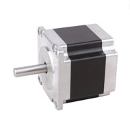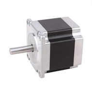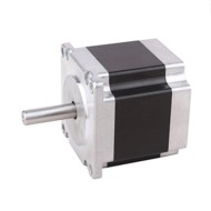
Nema 23 Stepper Motor Bipolar, 1.8 degree, 3A, 2 phase 4 wires
from
$69.15
Ex Tax: $69.15
- Stock: In Stock
- Model: SCJ009411
- SKU: SCJ009411
Products Sold: 0
Product Views: 645
Available Options
Ask a Question About This Product
- Description
Nema 23 Stepper Motor Bipolar, 1.8 degree, 3A, 2 phase 4 wires
Brief
Favorable price Nema 23 Bipolar stepper motor, 1.8 deg. step angle, 2 phase, allowing for a holding torque of 1.5Nm.
Description
Nema 23 Stepper motor, 1.5Nm in 64mm, 1.8 degree.
Specification
| Electrical Specification | Model | SOCOJE57HS64-3004 |
| Matched Driver Model | SCJ009411(Click it to see more info) | |
| Step Angle | 1.8° | |
| Holding Torque | 1.5Nm | |
| Rated Current/phase | 3A | |
| Phase Resistance | 1.3Ω | |
| Inductance | 2.2mH | |
| Rotor Inertia | 380g-cm2 | |
| Physical Specification | Frame Size | 57 x 57mm |
| Length | 64mm | |
| Shaft Diameter | Φ8mm | |
| Shaft Length | 19mm | |
| Motor Leads | 4 | |
| Weight | 0.8kg | |
| Technical Parameters | Step Angle Accuracy | ±5% (full step, no load) |
| Resistance Accuracy | ±10% | |
| Inductance Accuracy | ±20% | |
| Temperature Rise | 80℃ Max. (rated current, 2 phase on) | |
| Ambient Temperature | -20℃~+50℃ | |
| Insulation Resistance | 100MΩ Min. 500VDC | |
| Dielectric Strength | 500V AC for one minute | |
| Shaft Radial Play | 0.02Max. 450g | |
| Shaft Axial Play | 0.08Max. 450g | |
| Quality Assurance | Warranty Period | 12 months |
| Certificate | CE, ROHs, ISO/SGS9001 |
Dimensions: (Unit=mm)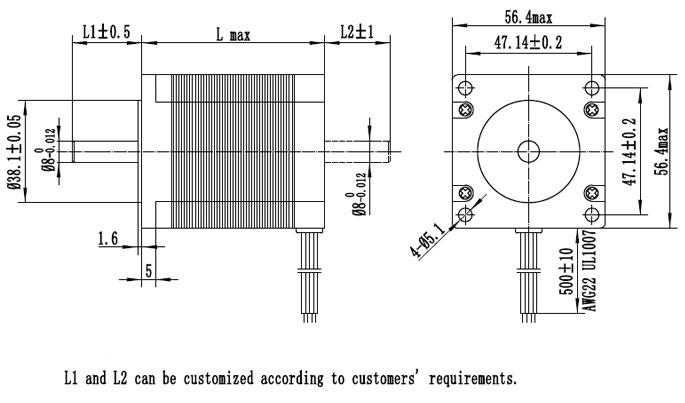
L Max=64mm, Shaft Length=L1-1.6mm, L1(Common)=20.6mm
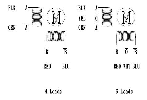
Wiring Diagram
Tips: Solutions to the step out of the stepper motor
- Calculate the torque of load and refer to the distance frequency diagram of the stepper motor,then check whether there is enough torque capability for the motor to drive load at the corresponding velocity. The comparison test can be implemented by replacing for the stepper motor with large torque at corresponding working velocity.
- At the start stage of stepper motor, it is necessary to speed up by gearing up gradually just like driving manual operation car. The acceleration and deceleration is insufficient, the step out will be caused. It is generally advised that the load rotational inertia under load should not be larger than 10 times of that of the stepper motor; otherwise the acceleration and deceleration process will be long.
- It is necessary to start or run the stepper motor at high velocity, the drive voltage should high and working current value should set enough large, or the step out also could be caused.
- Replace for the driver of another type to check if there is signal inference.
- At resonance, the stepper motor and its system have obvious noise and vibration. When its velocity is increased or reduced to a certain range, relevant phenomenon will be obviously mitigated or eliminated, which can be basically judged as the resonance problem. The resonance can be reduced through physical ways such as choosing the stepper motor with proper parameters and improving the performance of driver and using shock pad.
- If the signal of stepper motor driver is not matched with that of the controller, the phenomenon occurs that the displacement of location will be uniformly increased as the time passes by. Therefore, the signal identifying ways of the driver or controller should be changed to make the both matched.
7)There is certain error accumulation in synchronizing gear or reducer due to the precision problem, thus it is necessary to make rational compensation during the making process. - The control program often causes step out, so it is necessary to check whether there is something wrong with the control programming.
- Reviews
